Mounting
Securely mounting your Quest headset on your robot is crucial for reliable tracking and navigation. This guide covers mounting options, positioning considerations, and best practices.
Pose Origin
Before measuring ROBOT_TO_QUEST for your robot code, you need to know exactly where on the headset QuestNav reports its position. QuestNav uses a "Third-Eye Pose" — a point centered between the two lenses, on the plane created by the lens surface. It is not the center of the housing, the front face, or the strap.
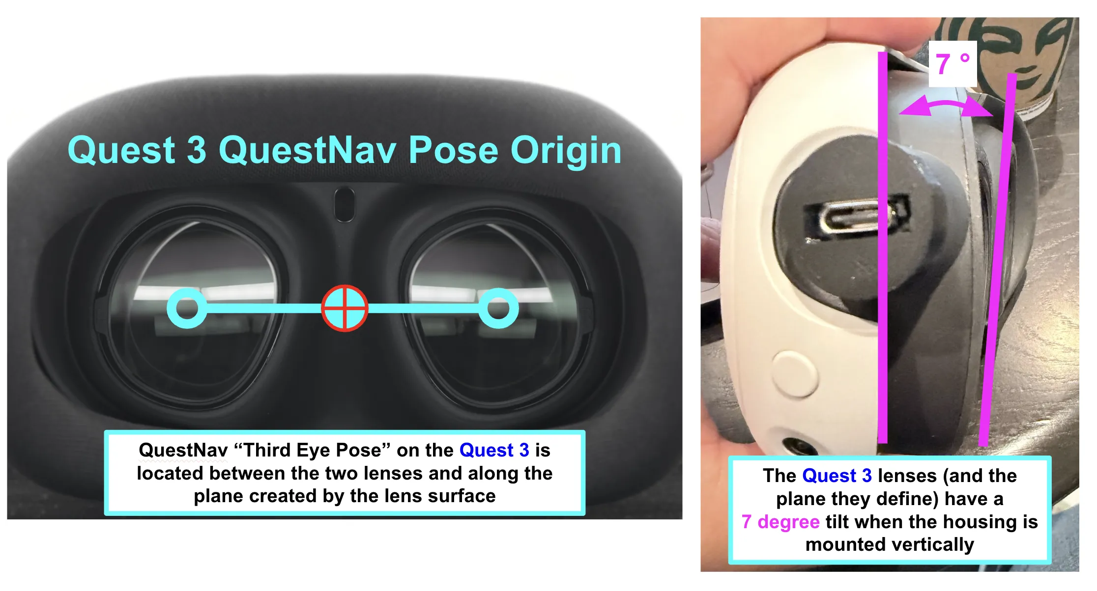
On the Quest 3, the lenses (and therefore the pose plane) are tilted 7° relative to the housing's front face. If you mount the housing vertically, the reported pose's local axes are tilted 7° forward. Either tilt the mount 7° backward to compensate, or include the 7° pitch in your ROBOT_TO_QUEST rotation. See Robot Code Setup for how to specify rotation offsets.
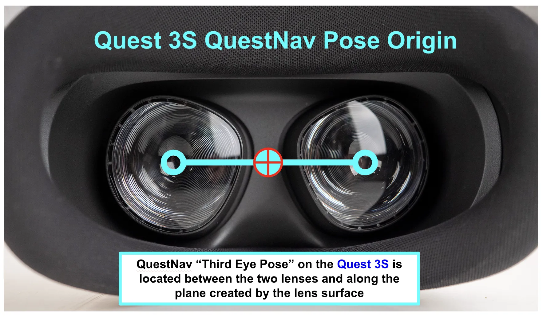
The Quest 3S does not have this tilt — its lens plane is parallel to the housing's front face, so a vertical housing produces a vertical pose origin.
Mount Design
QuestNav requires the Quest headset to be securely mounted to your robot in a stable, rigid location such as the robot base or frame that has a clear and unobstructed view of the field. Keep in mind that the headset's position directly correlates to your robot's position on the field, so allowing the headset to move independent of the robot will introduce position error.
We recommend using a 3D printed mount designed for your particular headset for this purpose.
The specific mount design you need depends on your Quest model. QuestNav is optimized for the Quest 3 and Quest 3S headsets, which have a slightly different form factor than older models.
3D Printed Mount Options
STLs and STEP files for both Quest 3 and Quest 3S headsets are available at the links below:
Quest 3S Headset Mount for Robots and Autonomous Vehicles
Quest 3 Headset Mount for Robots and Autonomous Vehicles
If you don't have access to a 3D printer, check with other local FRC teams, your school's engineering department, or local makerspaces that might offer 3D printing services.
Printing Guidelines
- Material: PLA+, PETG, or CF-Nylon filaments are recommended for durability and rigidity
- Infill: 25-30% minimum for structural integrity
- Layer Height: 0.2mm or finer for smoother surfaces
- Supports: Required for overhangs (on build plate only)
Avoid using ABS for printing mounts, as it will shrink and may crack under the vibration and impacts experienced during competitions.
Mounting Position
The optimal mounting position for your Quest headset depends on several factors:
Height Considerations
- Mount the headset at least 12 inches (30cm) above the floor
- Ensure the headset has a clear view of the surroundings
- Avoid mounting the headset where its view is largely obscured by motors or other robot parts that spin/move a lot
Mounting the headset too close to the ground can result in poor tracking as the cameras may only see the field carpet and nearby robot parts rather than distinctive environmental features. It also makes damage from robot-to-robot interactions more likely!
Orientation
The headset's orientation doesn't really matter for tracking quality, as long as the SLAM cameras have a clear view of their surroundings (see Field of View Requirements below). Mount the headset in whichever orientation best fits your robot: upside-down, sideways, rotated 90° or 180° relative to the robot's forward direction, or tilted at an arbitrary angle. QuestNav tracks identically in all cases.
The only requirement is that the rotation must be reflected in the ROBOT_TO_QUEST transform in your robot code, so reported pose data converts correctly to robot-frame coordinates. See Robot Code Setup for how to specify rotation offsets.
Field of View Requirements
The Quest tracks the world using SLAM cameras built into the housing. The headset fuses the feeds from all of these cameras to drive its visual-inertial odometry (VIO) solver. Tracking relies on those cameras seeing distinctive environmental features, so anything that blocks their view reduces the feature count available to VIO and degrades tracking.
There are two camera groups to keep clear.
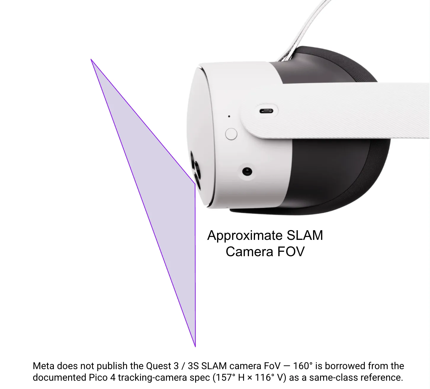
Front-facing SLAM camera points forward and slightly down:
Side-facing SLAM cameras point left and right at the sides of the housing:
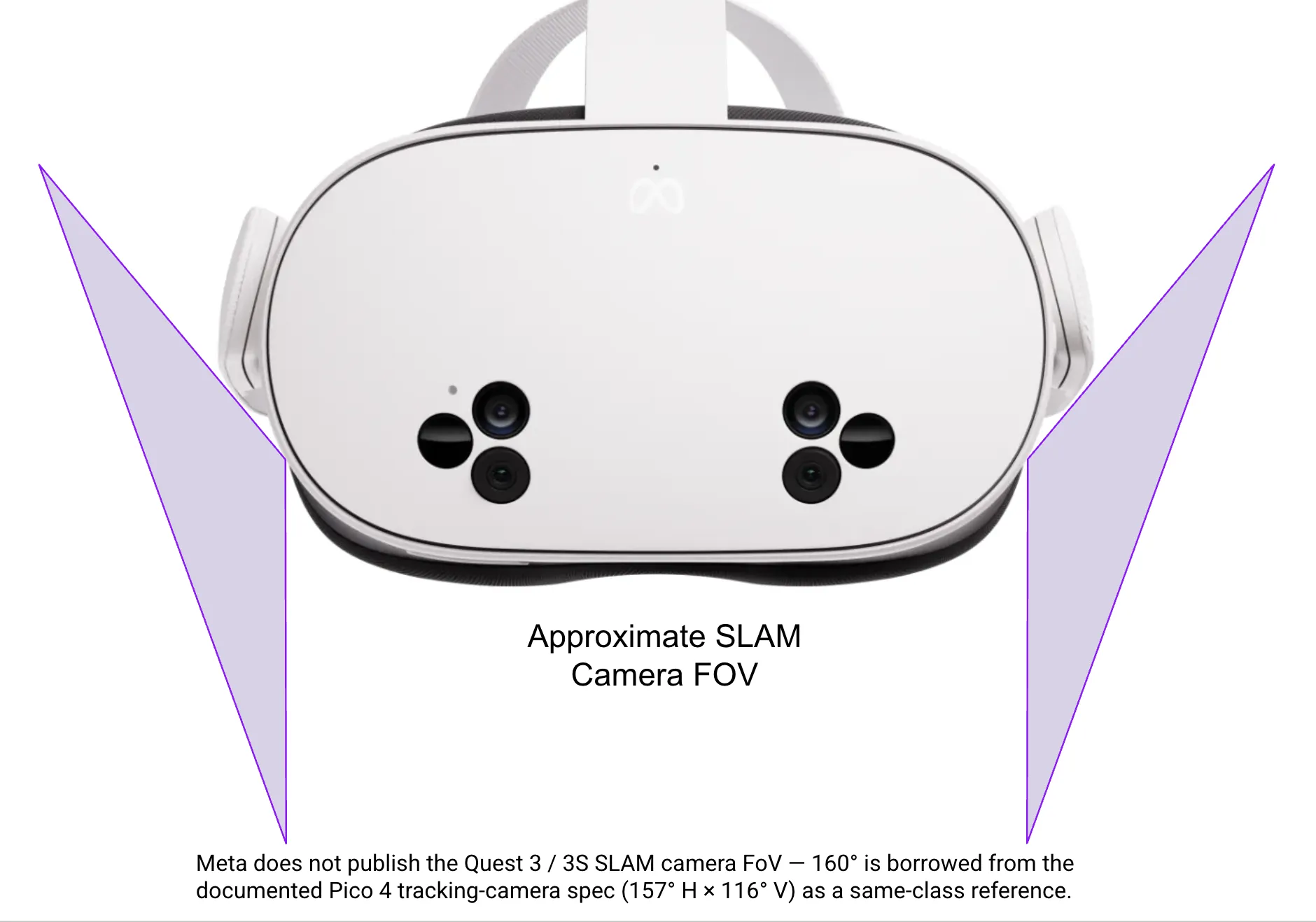
Meta doesn't publish official SLAM camera FOV specs for the Quest 3 / 3S. The 160° approximation shown here is borrowed from the documented Pico 4 tracking-camera spec (157° H × 116° V) as a same-class reference.
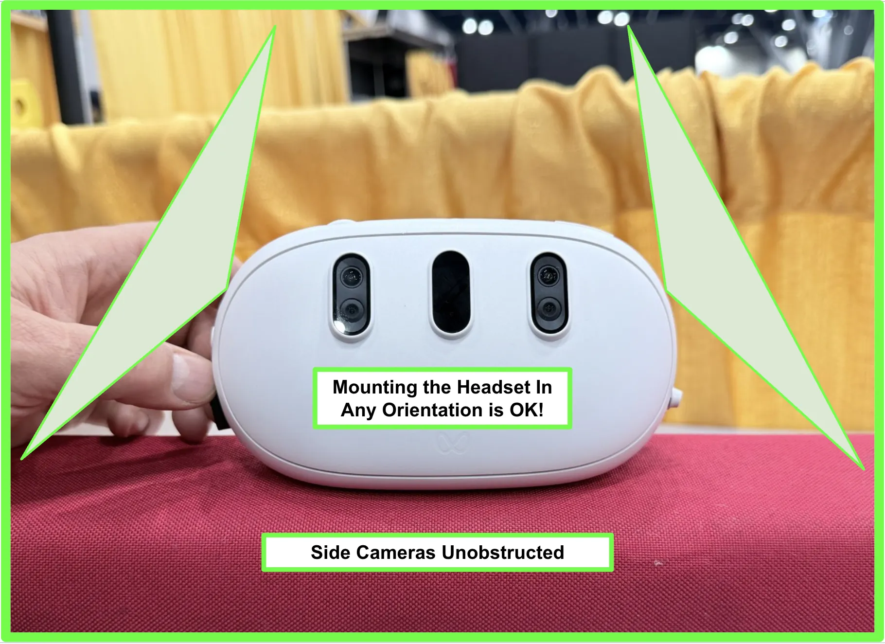
Good vs. blocked mounting
Mounting the headset in any rotation is fine as long as the camera FOVs stay clear:
Be careful that bumpers, mount geometry, or robot frame parts don't intrude on the FOV cones. Even partial obstruction reduces the trackable feature count and increases the risk of tracking re-initialization and pose jumps:
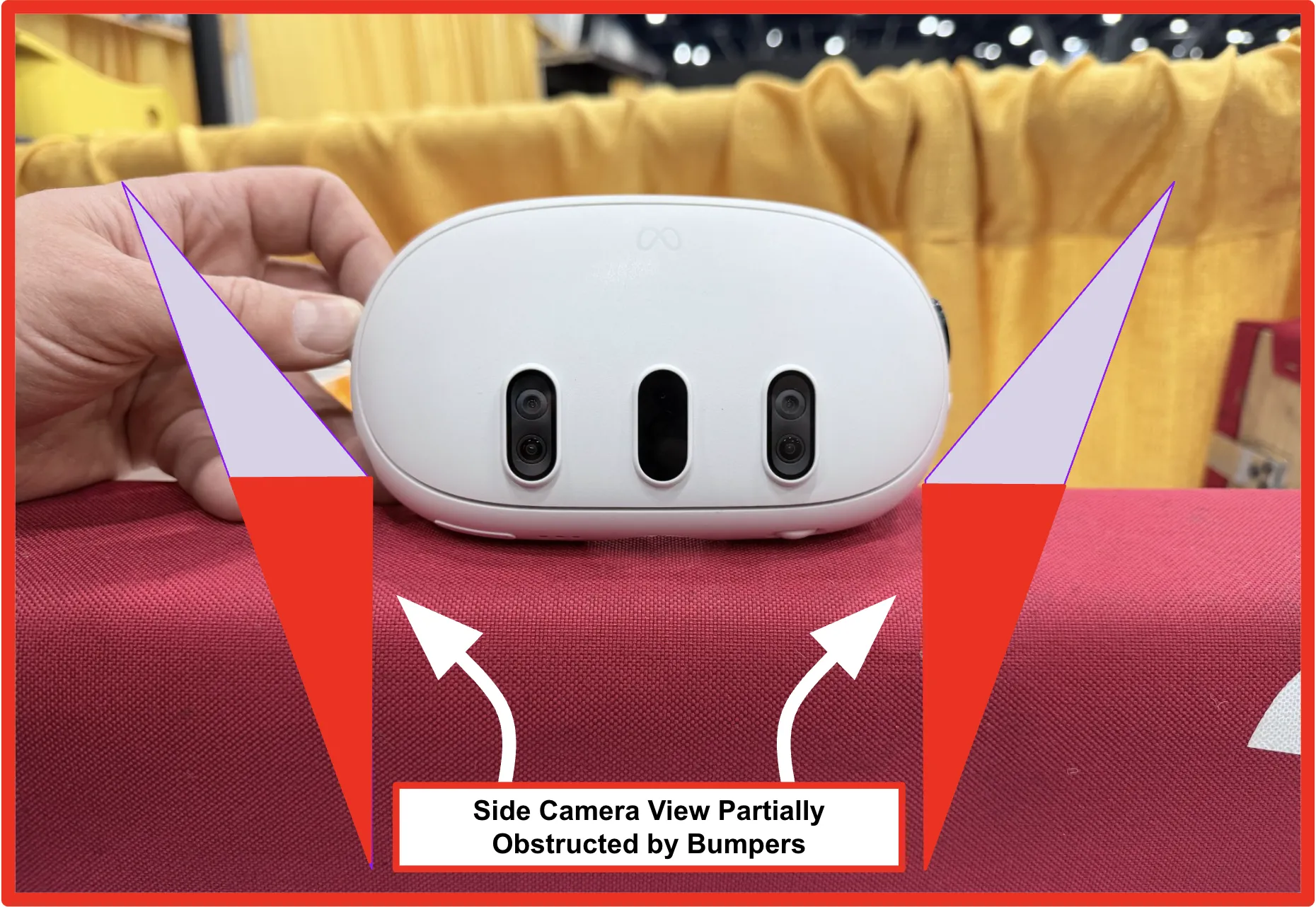
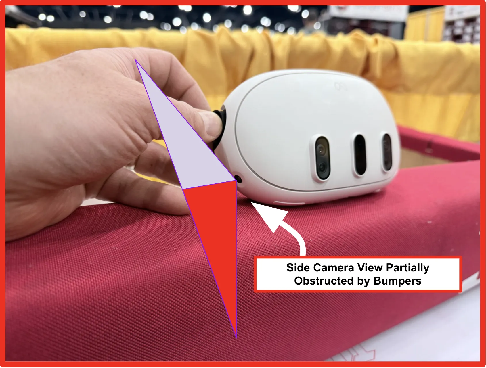
Obscuring one or more cameras will not render the system inoperable. Instead, position drift increases significantly and tracking performance degrades. It's all a sliding scale: the system won't "break", it just performs worse the more its view is restricted.
Secure Attachment
Once positioned, the headset must be firmly secured to prevent movement or vibration:
Using Zip Ties
- Thread zip ties through the designated channels on the mount
- Carefully secure around the headset, avoiding excessive pressure on displays or buttons
- Keep zip ties clear of the SLAM cameras on the front and sides of the housing
- Use at least 4 zip ties for redundancy (two on each side)
- Trim excess zip tie length to prevent interference
Never route a zip tie across a SLAM camera lens. Anything covering a camera completely blocks its contribution to the VIO solution and severely degrades tracking. See Field of View Requirements for the camera locations.
Overtightening zip ties may lead to increased tracking drift, since the added mechanical strain deforms the housing and can apply pressure to sensitive areas of the device. Secure firmly but without straining the plastic casing.
Additional Security
- Use lock washers or thread locker on mount-to-robot bolts
- Perform a "shake test" to ensure the headset doesn't move
Wiring Considerations
When mounting, plan for cable management:
- Ensure the USB-C port is accessible for the Ethernet adapter
- Leave sufficient slack in cables to prevent tension
- Secure cables along the mount to prevent snagging
Cables under tension can damage connectors or pull loose during matches. Always include a small service loop and secure cables to prevent strain.
Testing Visibility
After mounting, verify that the Quest has clear sightlines:
- Visually inspect the mount with the headset installed. Compare the physical mount geometry against the FOV cones in Field of View Requirements and look for anything (bumpers, frame members, intakes, robot bumpers, cabling) that intrudes on a cone.
- Power on the headset and drive realistic motion with the robot. Run turns, quick stops, and full-speed lane changes while watching
QuestNav/Tracking,trackingLostEvents, and the reported pose in AdvantageScope or the WPILib simulation GUI. Lost tracking or sudden pose jumps usually point at FOV obstruction or vibration.
Don't use the headset's passthrough display as a proxy for the SLAM cameras' field of view. The passthrough FOV is significantly narrower than the SLAM camera FOV, so passthrough can look fine while large portions of the actual SLAM FOV are blocked.
Next Steps
Once your Quest is securely mounted, proceed to the Wiring section to learn how to connect your headset to the robot's network.